mgProject 2: "Interactive Input/Output with Low-Tech"
The Inertial Extemporization Device: A fun, vigor-based, low-cost musical instrument!
Written March 20, 2023 • Last edited March 29, 2023
Intro
The goal of this project was to create an interactive device that used either a low-tech input or low-tech output system. Reed and I built a paper cube with copper-taped insides (low-tech input) that plays notes from the whole tone scale on a piezo buzzer based on how quickly it's being shaken. Our process is described in detail here.
Reference Links
- How to make an origami cube
- Just intonation for getting relative frequencies and ratios
- More about the whole tone scale
- More about the twelfth root of two in music theory
- Final product demo video!
03/20/2023
Today, we brainstormed and came up with a list of as many low-tech inputs and outputs as we could, in addition to what functionality our final product might have in general:
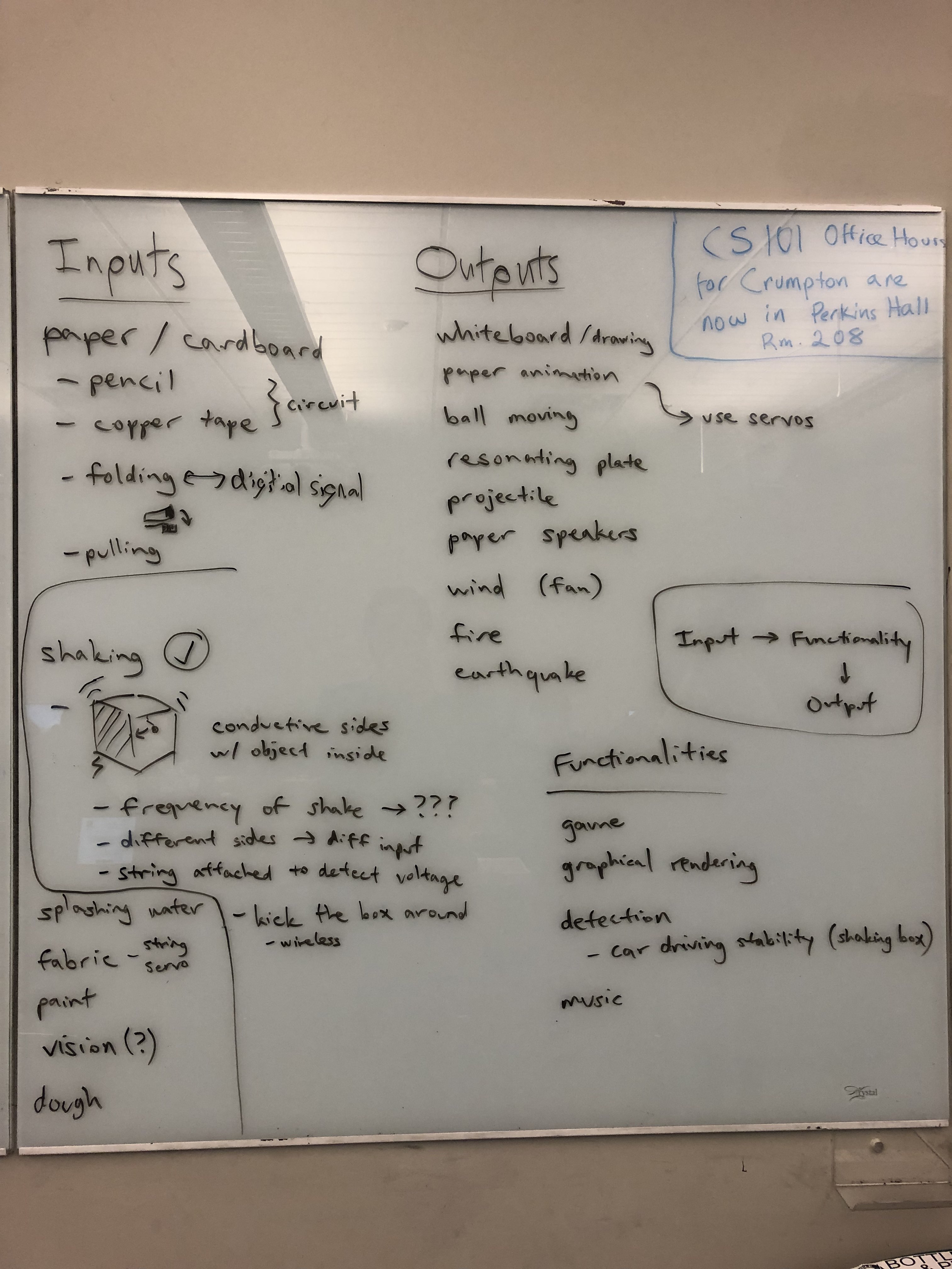
We easily agreed that some kind of shaking box with conductive sides was the low-tech input idea we wanted to explore further, and we will figure out more details later this week. We definitely need to buy something like copper tape and will maybe use a metal ball on a conductive string (attached to the inside of the box) to get a better capacitive reading. Thinking about the prototype, we imagine a 3D-printed box, perhaps with a place to hold the Arduino. Later, we need to also consider what functionality we want to get out of this box.
03/21/2023
We explored more design ideas and potential features based around the shaking box input:
- The string can go to the Arduino through a small hole modeled in the top, and we can secure the string with tape on the outside. The Arduino could go outside of the box.
- Functionality ideas:
- Rhythm game with 4 sides where you make the ball hit the side of the box corresponding to the display on the LED matrix
- A game involving rotating the box along a different axis such that the ball rests on one of the sides with copper tape, display on LED matrix
- Making use of the frequency of the shaking:
- Flappy Bird clone game where the frequency of the shaking determines the player's upward velocity, display on LED matrix
- Musical output where the frequency of the shaking determines the frequency of the pitch
03/23/2023
We pitched our main idea of the shaking box along with the two possible output modes we considered ("gravity-powered gyroscope" and "shaking sensor") to our design critique partner group and got some good feedback. They liked the idea and how there is significant movement involved, making it interactive. However, some of our functionality ideas were too game-focused, and we should keep it simple. That way, the product would function without a full game having to be developed again and displayed properly. All of us agreed upon the musical idea being a good output path to explore further, since it's a simple use of the output but gives us more time to refine and iterate on the system as a whole.
As far as prototypes go, we were unable to get a hold of copper tape, so we could not explore some of the other options like paper circuits and start building prototypes in parallel. We were able to test the basic string-ball-copper system today with a multimeter though:
03/27/2023
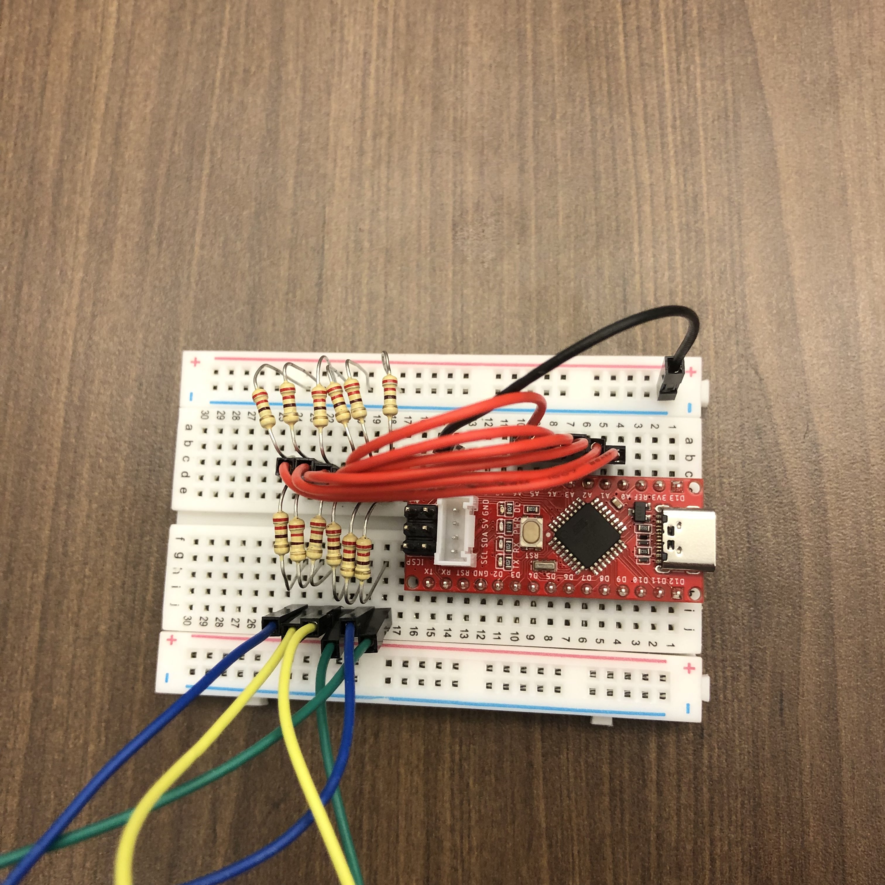
The copper tape we ordered still hadn't arrived yet, so in our meeting today, we just prototyped the rest of the system. We hooked up a similar string-ball-copper system to the Arduino this time and checked what kind of reading we could get from it. Our first attempt involved hooking up the six input pins to pads that we would touch with a +5V source. However, this did not work, and we were seeing unreliable readings from the sensor. This is because the input pads were not grounded. We fixed this by using a voltage divider circuit, making it so that the input pins were always grounded and could still connect +5V to the pad without causing a short. We can use analogRead() to get a reliable value from this.
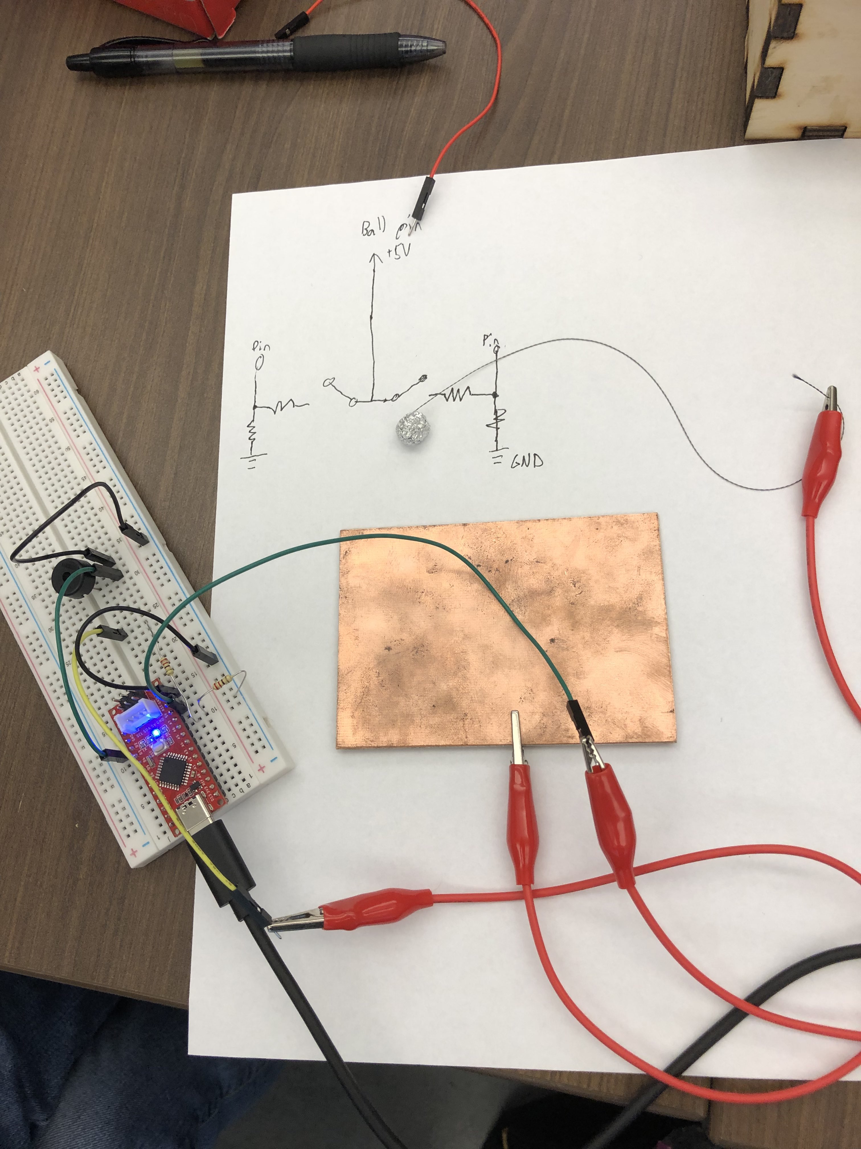
After printing and observing the results, we added a buzzer to the circuit to experiment with the sound output. We learned that with the current foil ball, it wasn't heavy enough to maintain reliable contact with the copper plate for readings, but also we considered the rigidity of the plate here to be another factor, so we decided the actual box needed to be made out of something more flexible like paper and we would use something heavier for the ball. Reed pointed out that we have magnets in our kit that might give us the desired weight and be small enough to be wrapped in foil (to give it a more uniform shape) and put in the box.
#define COPPER_PIN1 A6
#define BALL_PIN 10
#define BUZZER_PIN 2

// the setup function runs once when you press reset or power the board
void setup() {
  pinMode(BALL_PIN, OUTPUT);
  pinMode(BUZZER_PIN, OUTPUT);
  digitalWrite(BALL_PIN, HIGH);

  // initialize serial communication at 9600 bits per second
  Serial.begin(9600);
}

// the loop function runs over and over again forever
void loop() {
  int copperPin1Read = analogRead(COPPER_PIN1);
  //Serial.println(copperPin1Read);

  if(copperPin1Read > 100)
    tone(BUZZER_PIN, 1024);
  else
    noTone(BUZZER_PIN);

  //delay(10);
}
03/28/2023
We created the paper cube today. Reed's background in origami helped inspire this idea, and we followed this guide to create it one side at a time.
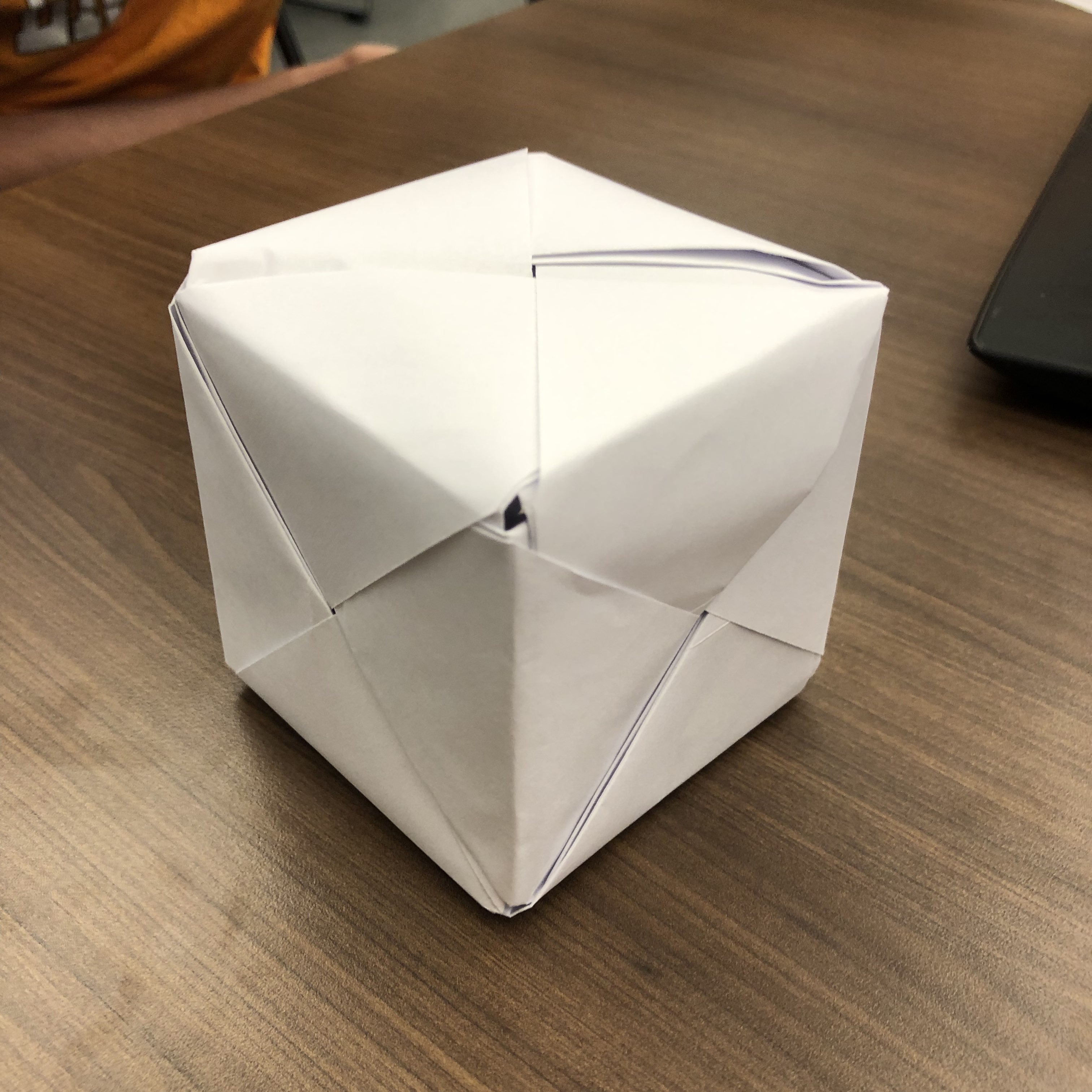
We also protoyped a new ball using the magnets, getting roughly the size and weight we were looking for. We tested the durability of the box and "ball" and how well the string was able to stay on. The origami flaps made it easy to access the inside from any side and disassemble the box if needed, such as for putting on the copper tape and future rapid prototyping.

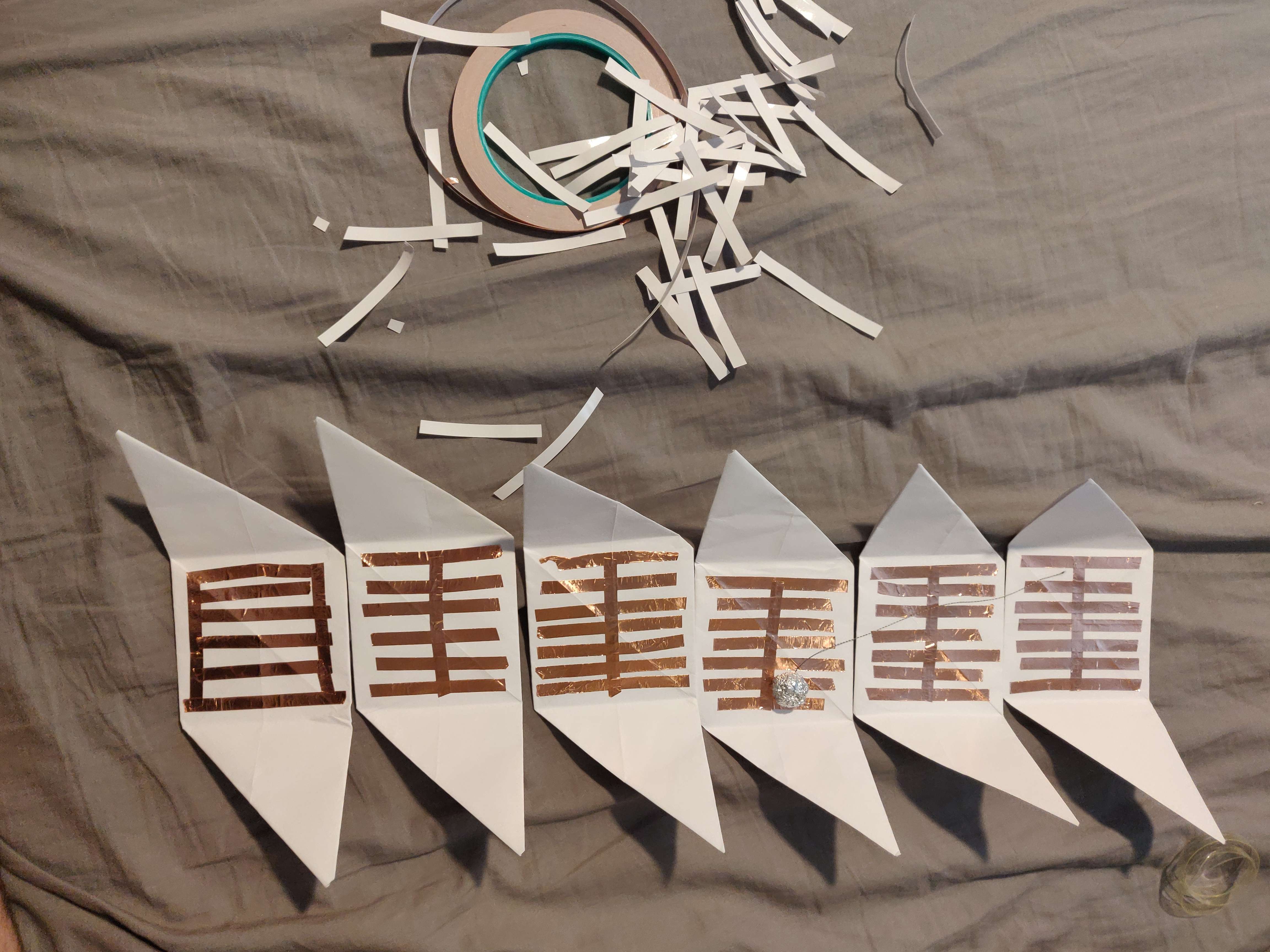
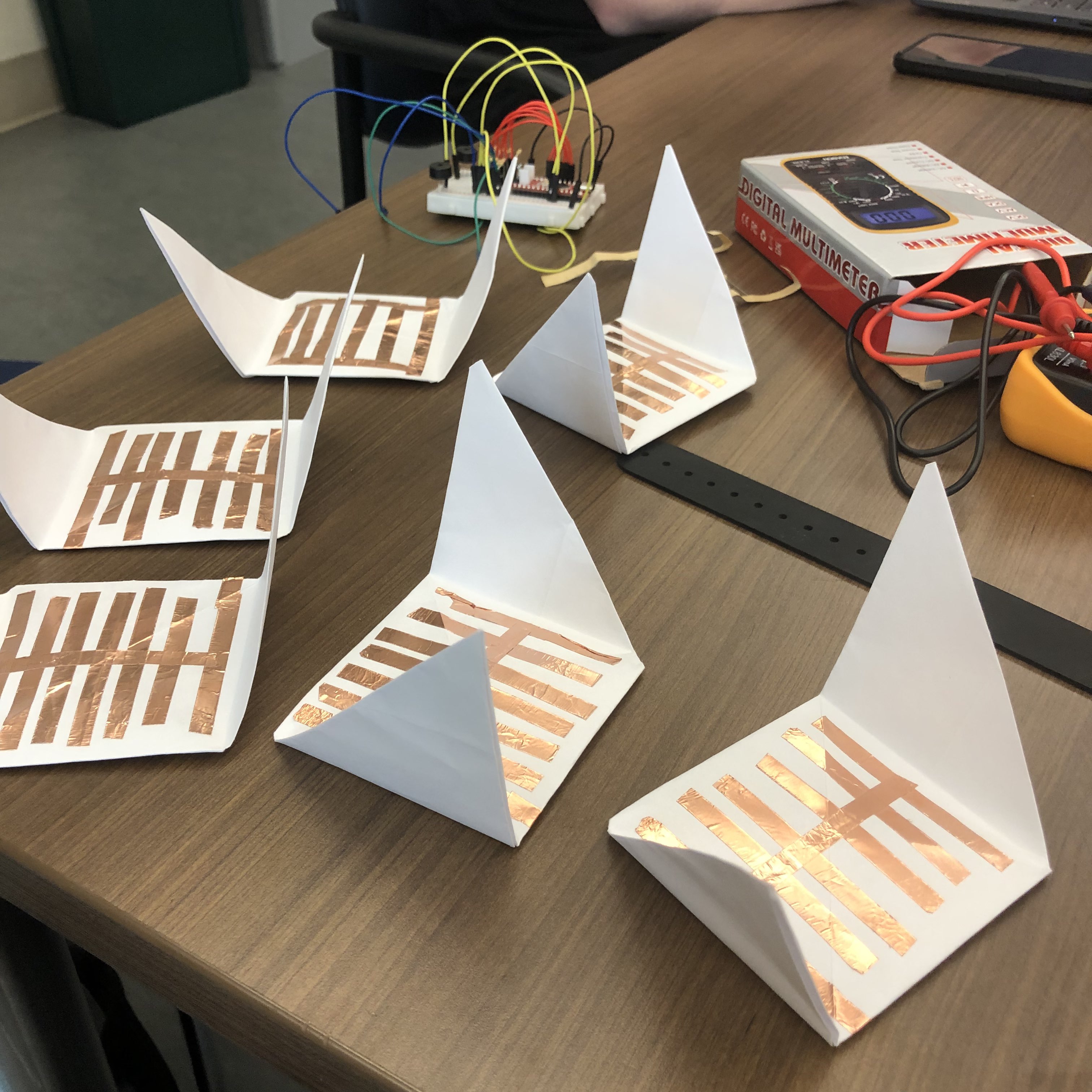
The copper tape finally arrived later in the afternoon, and Reed started putting it on the sides of the box:
Reed also wrote some initial code for testing the connection detection between the +5V source and the input pin, but we will wait until tomorrow to put everything together.
03/29/2023
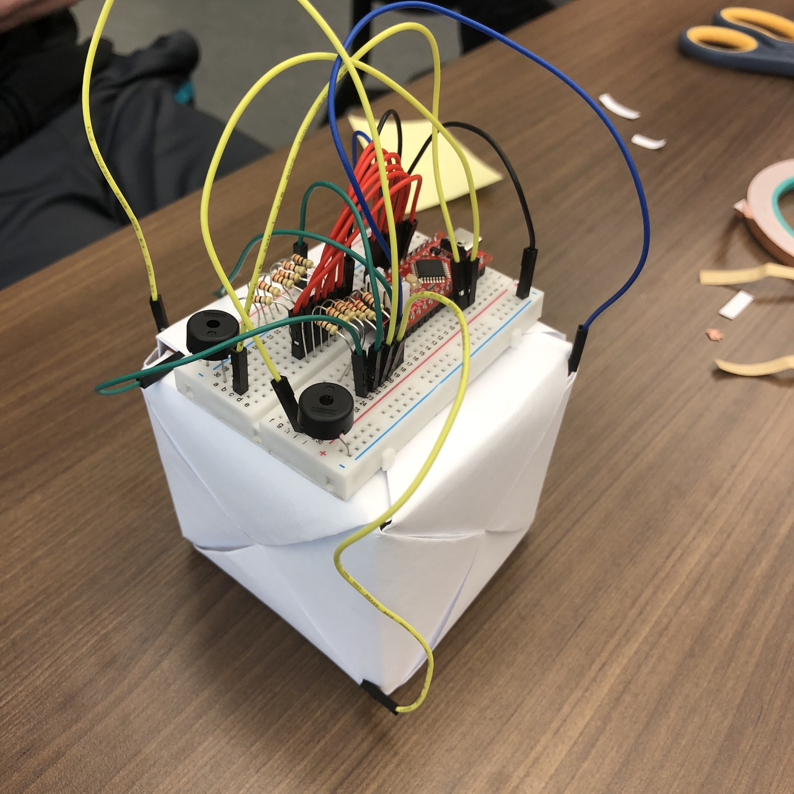
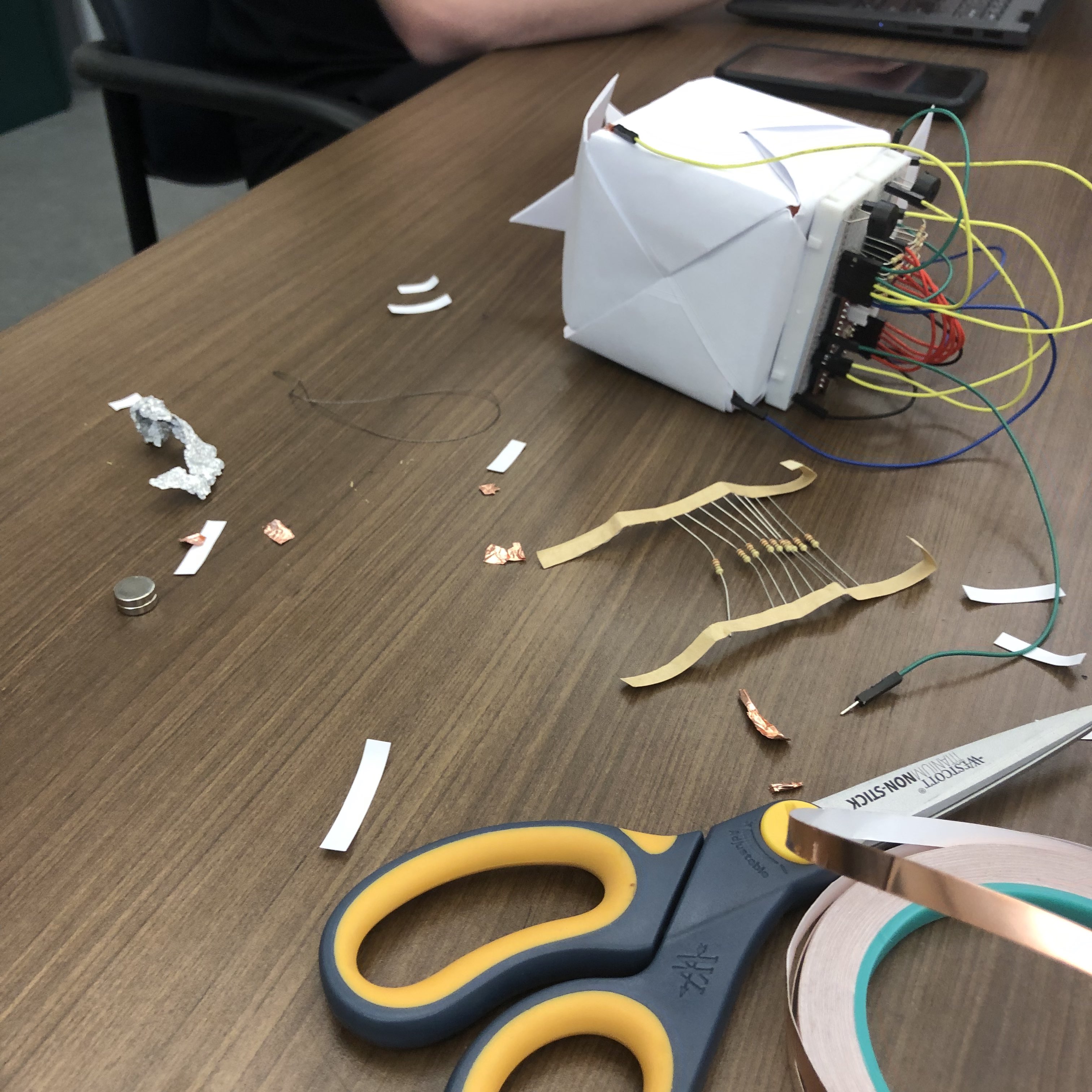
Today is the day to complete our prototype. We created a circuit with six voltage dividers to hook up each of the sides to:
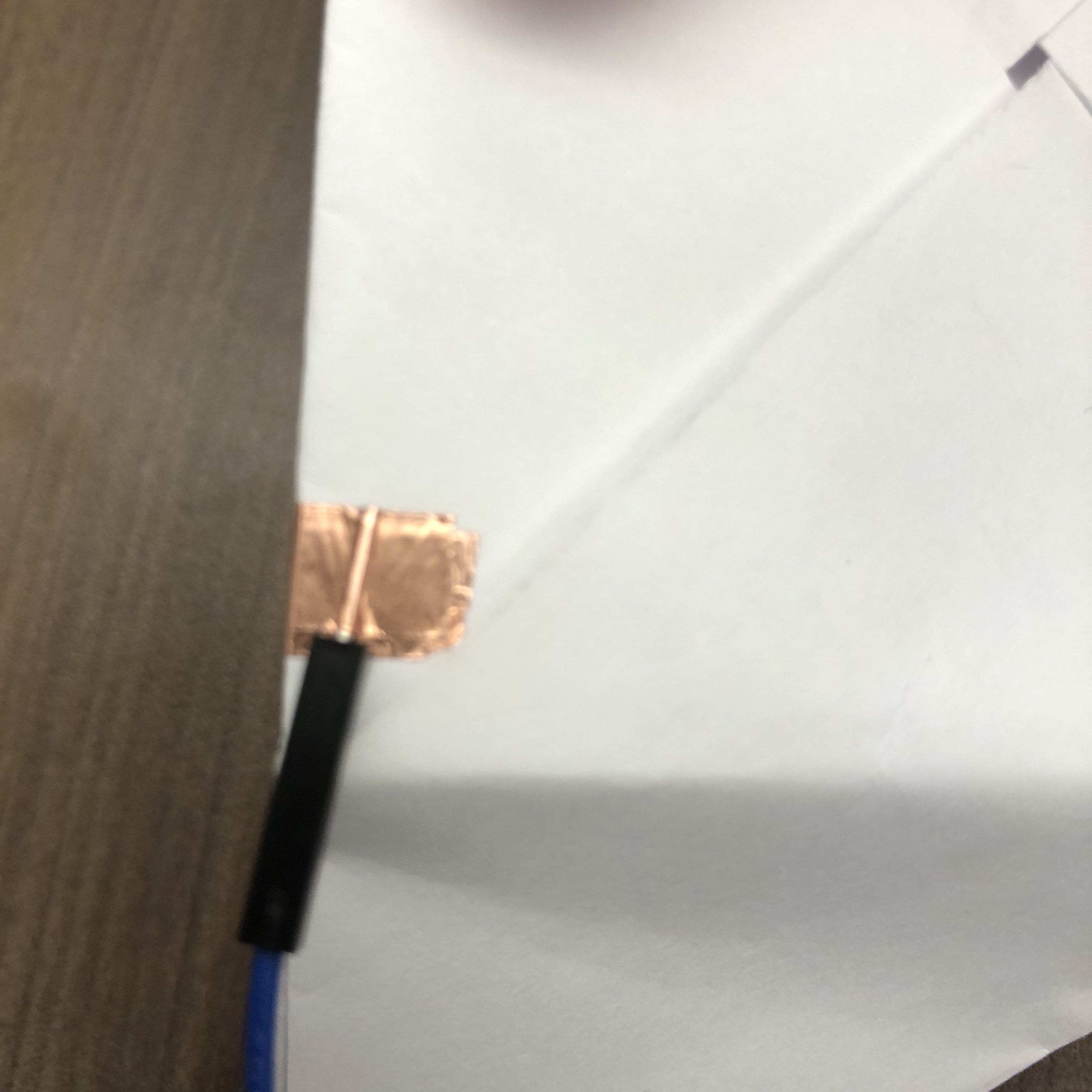
Then we taped breadboarding wires to each of the copper contacts of the six cube pieces and assembled it. Thankfully, the cube pieces still fit together easily without interference, and the copper contacts were not shorting to each other.
We could finally do a full integration test. We placed the ball inside the cube, closed it shut, and hoped for the best.
However, we encountered a small problem shortly after testing: it turns out that magnets are magnetic.
The magnets we added to the ball for more weight were attracted to something like the metal in the breadboard, and it would stick to the top of the cube and not move around without a strong shake to get it unstuck.
To alleviate this problem, we had to find another small, heavy, non-magnetic object to put in the foil ball. After some brainstorming and rummaging through our limited materials, we considered using loose change. We did not have any already on hand, so instead of begging from people, we cleverly (antisocially) acquired some from the Min Kao 3rd floor vending machine by feeding it a dollar, having the machine unexpectedly refuse to give the money back, and buying an item with a credit card—which added credit for one drink, which then caused it to eject 4 quarters in change. Nice.

With the energy of Mello Yello®, we rebuilt the foil ball using two quarters inside instead, and it worked fantasically! We were able to get a signal from each of the six voltage dividers, and it loosely followed the ball moving around as we rotated the cube.
Our first implementation idea with this mechanism was a musical device that played different notes depending on which side the ball was touching. We initially wanted two buzzers to play at the same time since the ball was now big enough that it could be touching multiple sides at once, and we wanted to play different musical intervals (have the buzzers harmonize with each other). Unfortunately, it turns out that simply isn't possible with tone(). We settled on testing with each side corresponding to certain frequencies with nice ratios:
if(r1 > 100) {
  tone(BUZZER_PIN, 500);
} else if(r2 > 100) {
  tone(BUZZER_PIN, 625);
} else if(r3 > 100) {
  tone(BUZZER_PIN, 750);
} else if(r4 > 100) {
  tone(BUZZER_PIN, 1000);
} else if(r5 > 100) {
  tone(BUZZER_PIN, 1250);
} else if(r6 > 100) {
  tone(BUZZER_PIN, 1500);
} else {
  noTone(BUZZER_PIN);
}
We decided to scrap this idea and go back to shake-based controls over gyro-based controls. This time, our input would be a scalar value that naturally rests at zero and degrades back to zero over time. By shaking the box, this value would increase, and we accomplish this by seeing when the voltage dividers change state. We hooked up this new control signal to a buzzer to auralize the input. We programmed the buzzer to remain silent when the box is at rest and play tones according to a music-math-based formula (in the code at the bottom) when it detects the changing states:
This was a good start, but it did not sound how we expected. We tuned it and also found a few related bugs so that now when it gets shaken, it starts going up a whole tone scale before quickly walking back down when the cube is no longer being shaken. We chose a whole tone scale because it has a nice, ethereal sound to it, and it was easy to implement (some base frequency multiplied by (⁶√2)ⁿ, where n is a natural number representing each note in the scale). More in the references at the top.
After hearing it work, we were incredibly pleased with the results. The sound it produced felt quite natural. Take a listen for yourself!
If you're interested, here's all the code. Enjoy!
mgP2.ino
#define SIDE1 A1
#define SIDE2 A2
#define SIDE3 A3
#define SIDE4 A4
#define SIDE5 A5
#define SIDE6 A6
#define BALL_PIN 3
#define THRESHOLD 100
// 12th root of 2 = 1.05946309436 (chromatic), 6th root of 2 = 1.12246204831 (whole tone)
#define WHOLE_STEP_RATIO 1.12246204831
#define BASE_FREQ 400
#define MAX_CHANGE 30

void setup() {
  Serial.begin(9600);

  // Initialize the pins we need -- 6 voltage dividers and 1 buzzer
  pinMode(SIDE1, INPUT);
  pinMode(SIDE2, INPUT);
  pinMode(SIDE3, INPUT);
  pinMode(SIDE4, INPUT);
  pinMode(SIDE5, INPUT);
  pinMode(SIDE6, INPUT);

  pinMode(BUZZER_PIN, OUTPUT);
}

bool touches[6] = { 0 };
bool prevTouches[6] = { 0 };
int change = 0;

void loop() {
  int r1, r2, r3, r4, r5, r6;

  // Read the voltage dividers
  // With our setup, we have a 220Ω resistor on each side, so the reading will be 512 when connected and 0 when disconnected
  r1 = analogRead(SIDE1);
  r2 = analogRead(SIDE2);
  r3 = analogRead(SIDE3);
  r4 = analogRead(SIDE4);
  r5 = analogRead(SIDE5);
  r6 = analogRead(SIDE6);

  char buffer[100];
  sprintf(buffer, "%d, %d, %d, %d, %d, %d", r1 > 100, r2 > 100, r3 > 100, r4 > 100, r5 > 100, r6 > 100);

  Serial.println(buffer);

  // Check if the voltage dividers changed state
  for(int i = 0; i < 6; ++i) {
    prevTouches[i] = touches[i];
  }

  touches[0] = r1 > THRESHOLD;
  touches[1] = r2 > THRESHOLD;
  touches[2] = r3 > THRESHOLD;
  touches[3] = r4 > THRESHOLD;
  touches[4] = r5 > THRESHOLD;
  touches[5] = r6 > THRESHOLD;

  // Count the number of changes
  for(int i = 0; i < 6; ++i) {
    if(touches[i] != prevTouches[i]) change++;
  }

  if(change > MAX_CHANGE) change = MAX_CHANGE;

  Serial.println(change);

  if(change > 1) {
    int freq = pow(WHOLE_STEP_RATIO, change) * BASE_FREQ; // truncate it
    tone(BUZZER_PIN, freq);
  }
  else {
    noTone(BUZZER_PIN);
  }

  // Slowly decay the change value
  if(change > 0) change--;
  delay(100 - change * 3); // the higher the pitch, the faster it will Fall Off
}