mgProject 1: "Interactive 8x8 Gaming Machine"
<< Bit Shift >>: An interactive microcontroller game!
Written February 25, 2023 • Last edited March 9, 2023
Intro
The goal of this project was to create inventive input for playing a game we programmed to display on an 8x8 LED matrix. My partner Reed Semmel and I set out to build a "dodge the obstacles" kind of game and experimented with different forms of player interaction from there, and we ultimately settled on using two copper plates as touch sensors to move the player left and right. I detail our journey below.
Reference Links
- Arduino interrupt timer setup
- Shift register reference
- Capacitive touch sensing Arduino library
- Final product demo video!
02/25/2023
Reed figured out the pinout of the LED matrix and started to wire it up on our breadboards. The printed side of the matrix is where our pin number count starts from 1 at the bottom, going up to 12. The bottom of the opposite side starts counting up from 13 to 24.
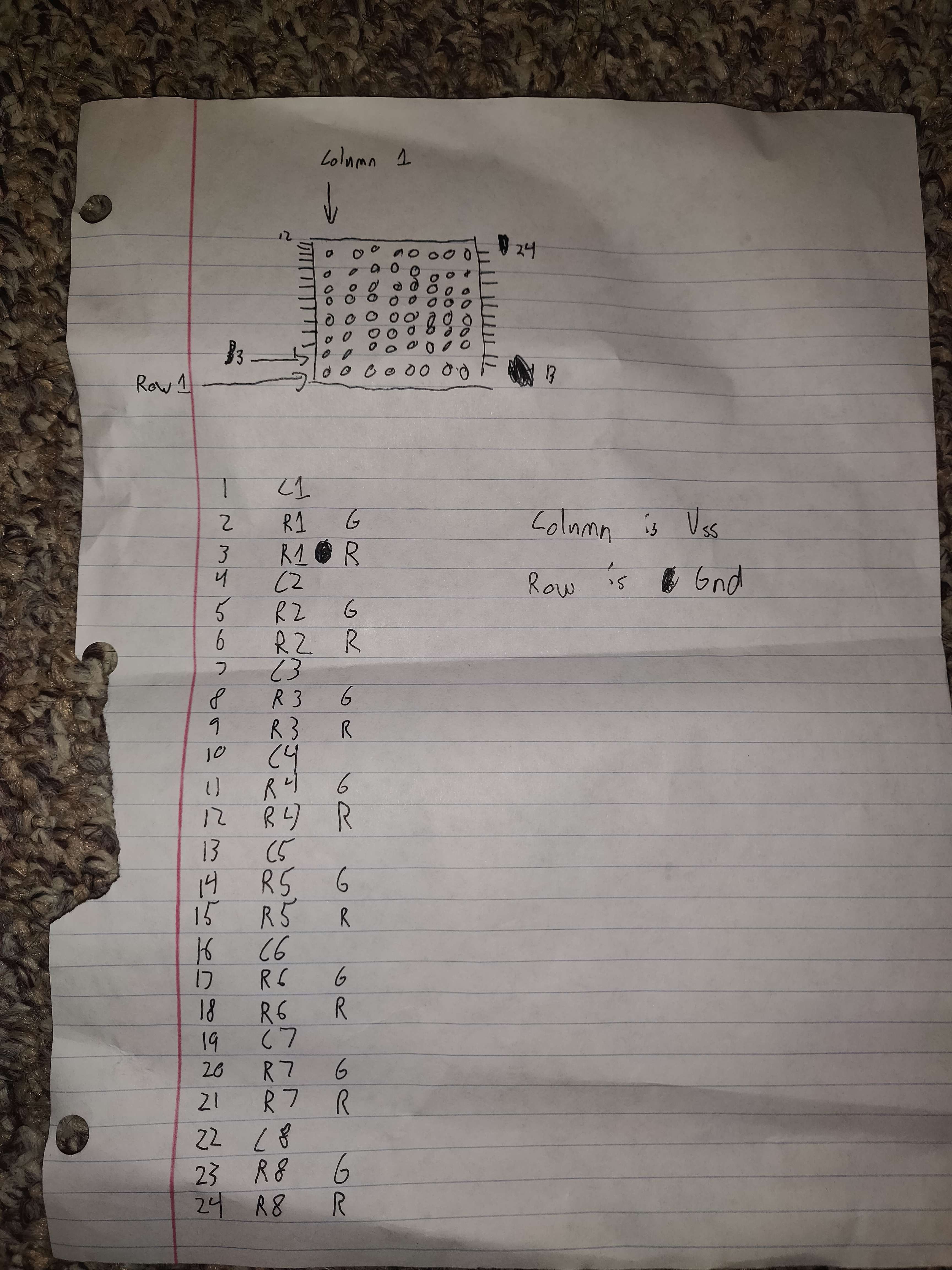
Here, the column pins (1, 4, 7, 10, 13, 16, 19, 22) are connected to a shift register and the red row pins (3, 6, 9, 12, 15, 18, 21, 24—each of which are offset two pins from their respective column pin) are connected to the Arduino with the resistors going to the row pins.
❝ This is pain❞
- Reed
02/26/2023
Today, Reed wrote some code to test the matrix. Thanks to the shift register, we can address the state of individual LEDs just by writing bits to matrixData, where matrixData[i] contains a bit representation of the state of row i+1. The shift register pins each had a corresponding column (Q0 = column 1, Q1 = column 2, ..., Q7 = column 8) and would be controlled by the shiftOut() call using the desired row state. Because of how the matrix is hooked up, we have to cycle through only lighting one row at a time. 7 of the 8 row pins connected directly to the Arduino are set to HIGH while one is LOW to allow a positive voltage through the LED coming from the shift register. The macro ISR() sets up a function signature that GCC will recognize to specifically set up as an interrupt service routine, and this allows the matrix to be continuously redrawn without any graphical bugs. It gets called once per millisecond, so it takes 8ms to render one frame.
The code below simply repeatedly swaps the data in rows 4 and 5 of the LED matrix:
// Row pins are pins [2, 10)
#define ROW(x) ((x) + 2)

// Shift register related pins
#define LATCH_PIN 11
#define CLOCK_PIN 10
#define DATA_PIN 12

void setup() {
  for(uint8_t i = 0; i < 8; i++) {
    pinMode(ROW(i), OUTPUT);
    digitalWrite(ROW(i), HIGH);
  }

  pinMode(LATCH_PIN, OUTPUT);
  pinMode(CLOCK_PIN, OUTPUT);
  pinMode(DATA_PIN, OUTPUT);

  // Set up interrupt timers
  // Taken from https://projecthub.arduino.cc/Marcazzan_M/6c0f6671-b431-4bd1-af94-c74e352e2252
  cli();

  // Set CTC mode for 1ms and enable the interrupt handler
  TCCR0A |= (1<<WGM01);
  OCR0A = 0xF9;
  TIMSK0 |= (1<<OCIE0A);
  // Set pre-scale clock to 1/64
  TCCR0B |= (1<<CS01);
  TCCR0B |= (1<<CS00);

  sei();
}

uint8_t currentRow = 0;
// Each index corresponds to a row's data
uint8_t matrixData[8] = { 0x1, 0x2, 0x4, 0x8, 0x10, 0x20, 0x40, 0x90 };

void loop() {
  uint8_t tmp = matrixData[4];
  matrixData[4] = matrixData[3];
  matrixData[3] = tmp;
  delay(500);
}

ISR(TIMER0_COMPA_vect) {
  // minus 1, except when 0 when it should be 7
  uint8_t prevRow = (currentRow - 1) & 0b111;
  digitalWrite(ROW(prevRow), HIGH);
  digitalWrite(LATCH_PIN, LOW);
  shiftOut(DATA_PIN, CLOCK_PIN, MSBFIRST, matrixData[currentRow]);
  digitalWrite(LATCH_PIN, HIGH);
  digitalWrite(ROW(currentRow), LOW);
  currentRow = (currentRow + 1) % 8;
}
02/27/2023
I tested ways to get green LEDs to turn on with the current setup, and I noticed dimness in rows where multiple red LEDs were on at the same time but not green. After some questioning and discussion, we realized we needed to rewire the board such that the resistors went between the column pins and the shift register rather than the row pins and the Arduino, since the matrix is being repeatedly drawn row by row, so no more than one LED per column is on at a given instant.
We also considered ways we could incorporate green for the player and decided that, since the player would be staying in the bottom row, we could simply hook up only row 8's green pin to the Arduino and implement control for it using a "row 9" in our bitmatrix. In the pinout above, "row 1" refers to the bottom row and "row 8" refers to the top row, but when playing the game, the system is oriented such that the player-controlled green LED in row 8 is physically nearest to the player. This gives the player a clearer view of the matrix as the wires are all over the other end.
02/28/2023
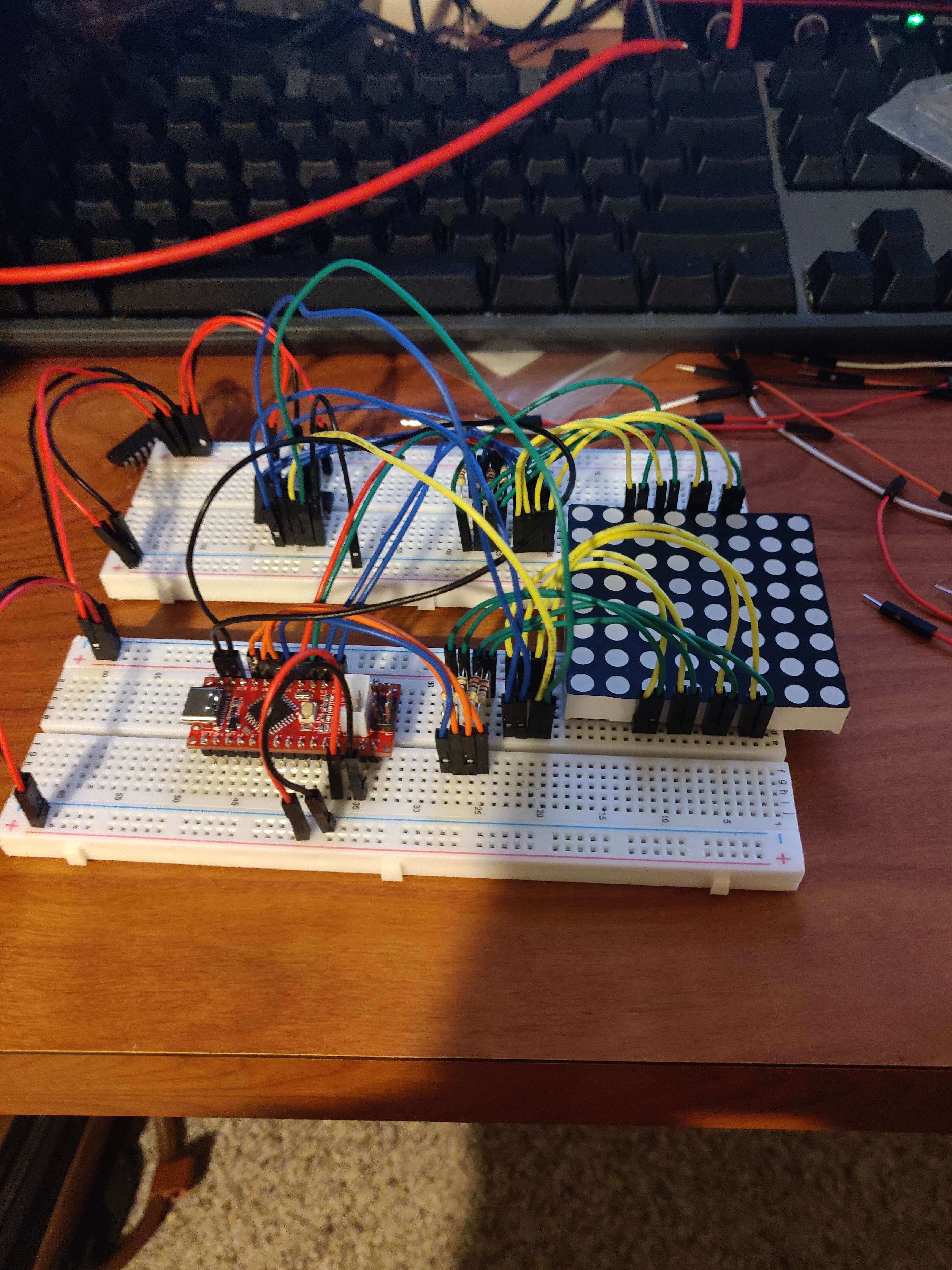
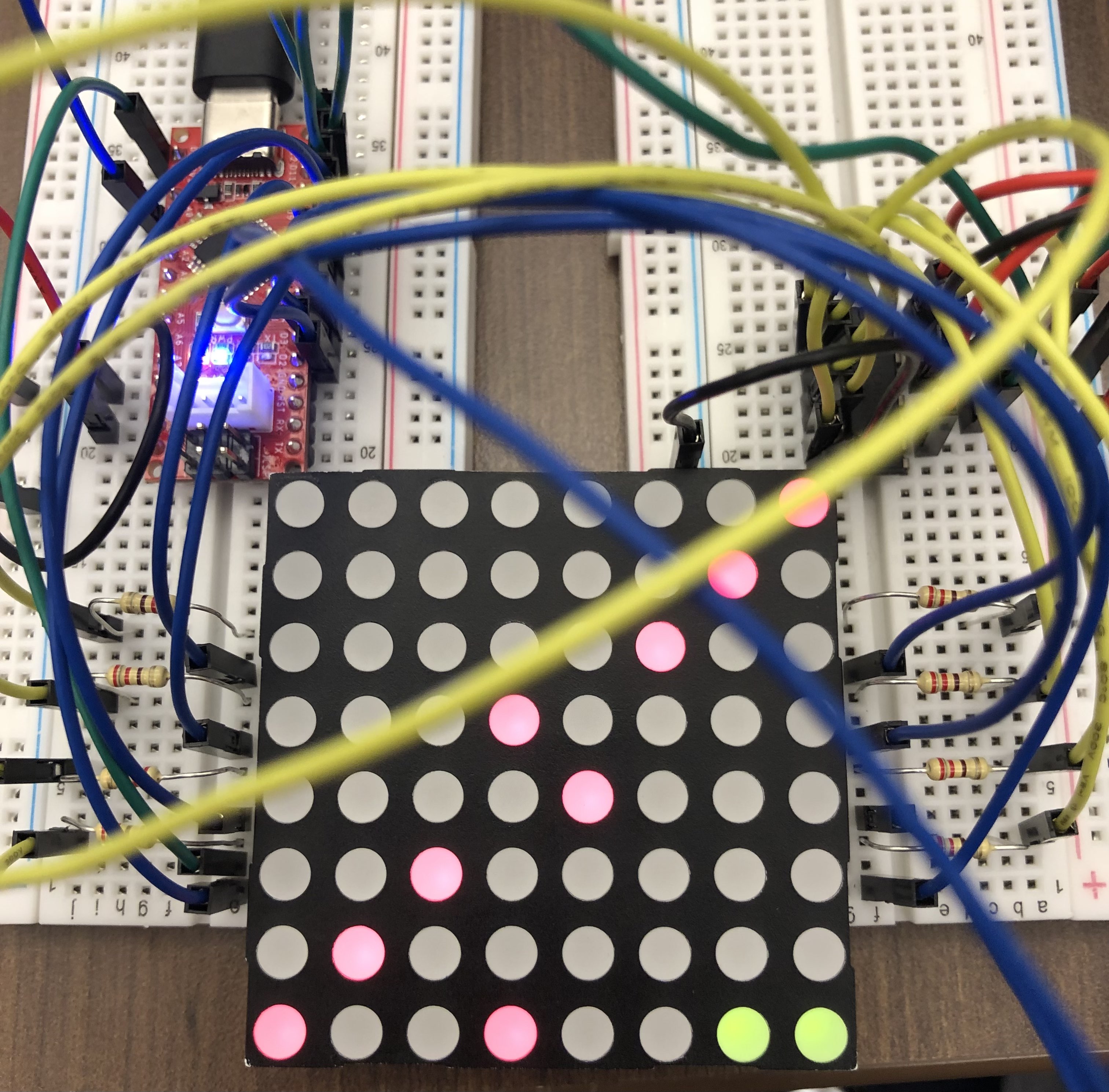
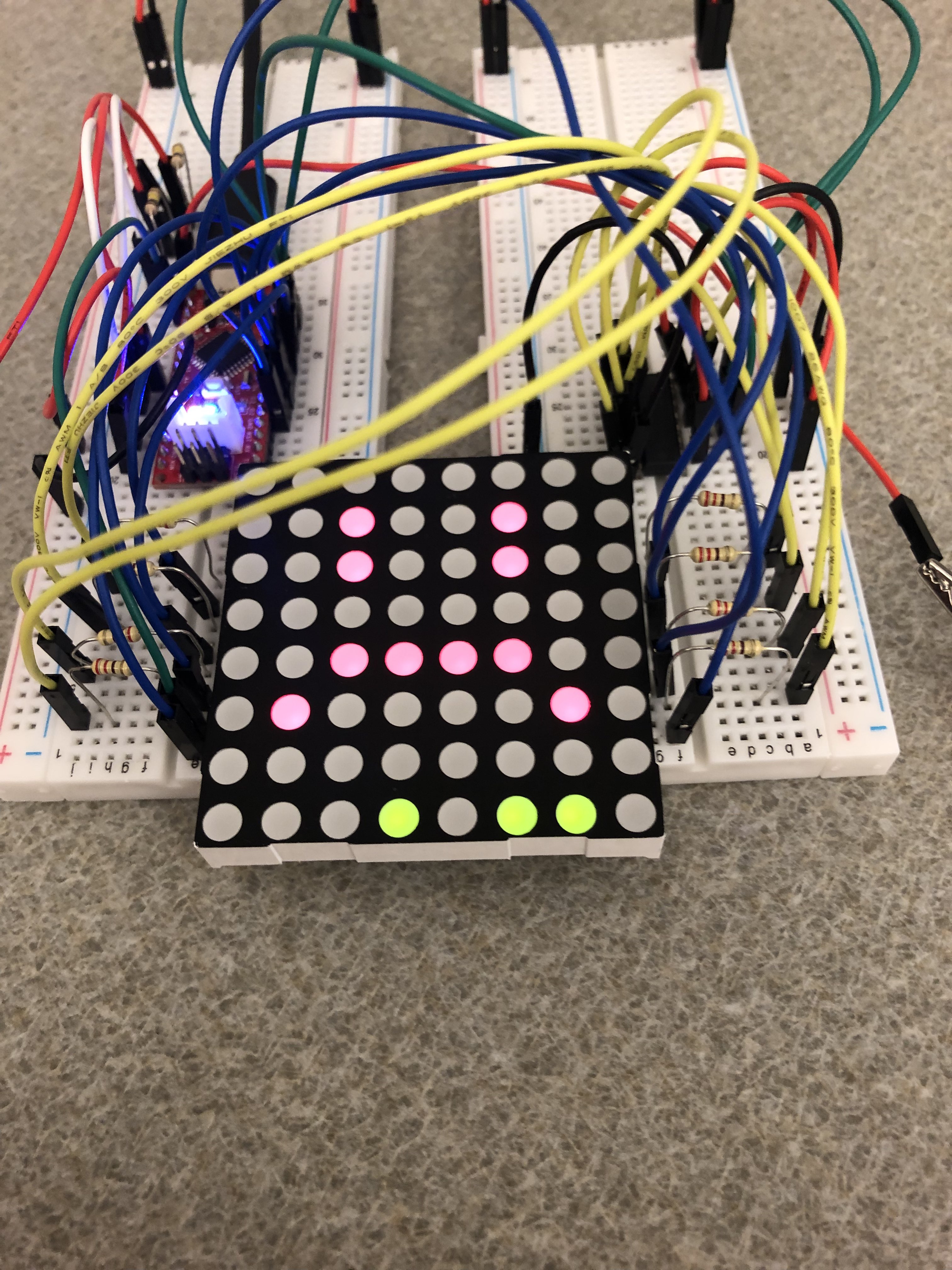
We rewired the circuit as described above as seen in the picture below:
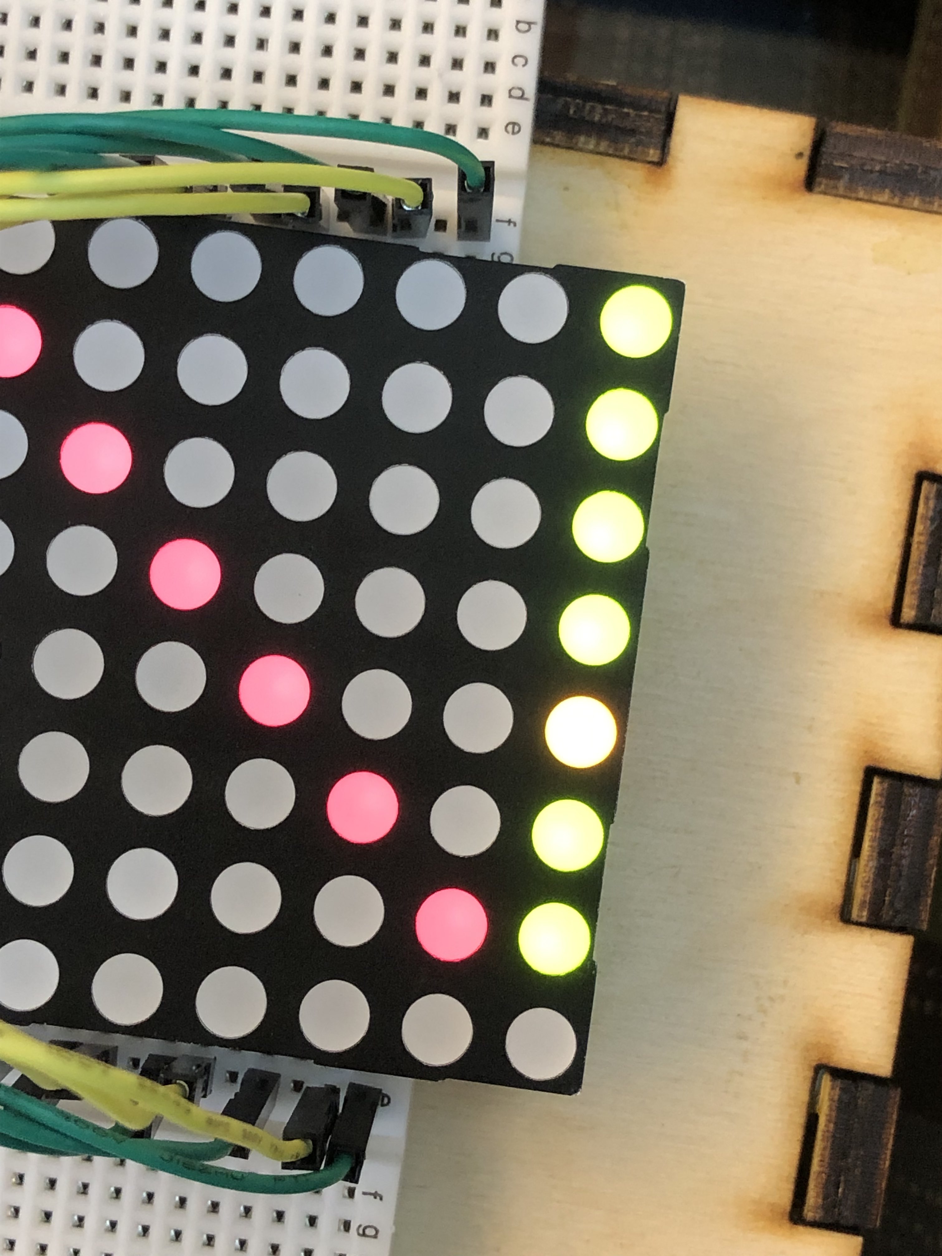
We then updated our code to make the dual red-green row work, and after some debugging and finding an off-by-one error, we were met with a nice two-color light display. The following image is the rendering of matrixData[9] = { 0x1, 0x2, 0x4, 0x8, 0x10, 0x20, 0x40, 0x90, 0x3 }:
Since we now had the ability to render the player, we started to think of ideas for user input. The first thing that came to my mind was using a photocell to control the position of the player—it was an inventive yet super simple way to allow us to later test the game logic if we could just get the player moving. After taking some readings to determine the light values we wanted to define the leftmost and rightmost positions, I created a voltage divider using the photocell as the varying resistance, mapped the value from analogRead() to a number between 0 and 7 and shifted the bit representing the player's position according to this output inside the ISR:
uint8_t lightLevel = analogRead(LIGHT_PIN);
shiftAmount = (lightLevel - 30) * (7 - 0) / (250 - 30) + 0;
matrixData[8] = (1 << shiftAmount); // between 30 and 250 -> between 0x1 and 0x80
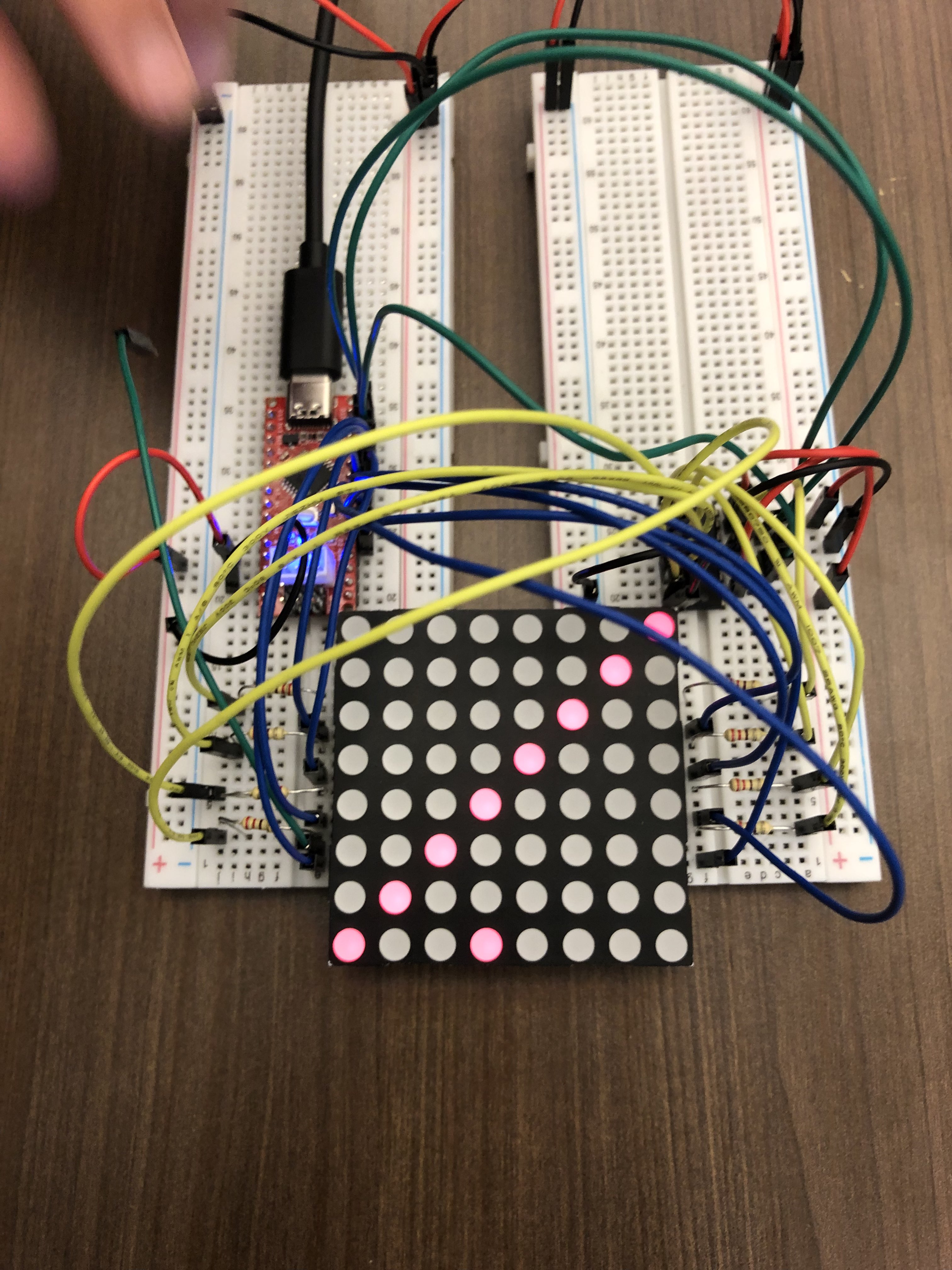
The initial result was a surprisingly responsive (but buggy) movement of the green LED. The player was seemingly wrapping back around, and due to the nature of the input and how the sensor works, you could get really fast sudden movements that basically skipped around sometimes:
My solution was to adjust the control range from [30, 250] to [100, 350] and clamp the input value to be in range so that the output behaved as intended and stayed in bounds for values too high and too low. For this, I wrote a function similar to the map() function, but it does clamping too (this was before I knew map() existed). Also this is when I realized that I originally made the lightLevel a uint8_t and didn't change it. Oops.
// Maps value from [minIn, maxIn] to [minOut, maxOut] and clamps value to be in range
uint16_t transform(uint16_t value, uint16_t minIn, uint16_t maxIn, uint16_t minOut, uint16_t maxOut) {
  if(value < minIn) value = minIn;
  else if(value > maxIn) value = maxIn;
  return (value - minIn) * (maxOut - minOut) / (maxIn - minIn) + minOut;
}
shiftAmount = transform(lightLevel, 100, 350, 0, 7);
At this point, we have implemented a fully working input for controlling the player, and we can start thinking about gameplay.
After our meeting, we discussed how our game logic would work, introducing the ideas of shrinking holes in walls and other ways of scaling the difficulty of the game as time passed. We planned to implement these features before our next meeting.
03/01/2023
Reed implemented the basic game logic code we brainstormed, and I helped debug it over Discord. Here's a basic rundown:
Each time loop() gets called, we call that a "game tick," and there is a defined (but variable) delay between ticks gameLoopDelay with a default starting value.
void loop() {
  // ...
  // Update the game difficulties before moving on
  tick++;
  updateDifficulties();

  // Progress the obstacles
  progressObstacles();

  // Add a new wall if it has been long enough
  if(ticksSinceLastWall >= ticksPerWall) {
    matrixData[0] = newRow(holeSize);
    ticksSinceLastWall = 0;
  } else {
    ticksSinceLastWall++;
  }

  delay(gameLoopDelay);
}
You'll notice a bunch of functions being called here.
In order to spawn a wall, the function newRow() creates a bitmask and shifts it into place like so:
// newRow creates a new row obstacle with a hole of holeSize in a random location
uint8_t newRow(uint8_t holeSize) {
  // 3 gets transformed to 0b111, 6 to 0b111111, etc.
  uint8_t mask = (1 << holeSize) - 1;
  // How far we move this mask along the screen
  // Make sure we don't chop some of it off by shifting too far
  uint8_t shift = random(0, 8 - holeSize + 1);
  // Build the wall
  return ~(mask << shift);
}
Then the return value gets assigned to matrixData[0]. This happens every so often (some number of ticks apart), determined by variables we can tune and scale.
Each game tick, the obstacles move one row closer to the player. Implementing this was as simple as moving data from one index to the next!
// Moves each row up one in the matrix
void progressObstacles() {
  for(uint8_t i = 7; i > 0; i--) {
    matrixData[i] = matrixData[i-1];
  }
  // The top row will become empty
  matrixData[0] = 0x00;
}
For difficulty scaling, we used a system based on the number of ticks that have passed:
// Change the global values relating to game parameters based on the current game tick
void updateDifficulties() {
  // Every 32 ticks, make the game go a little faster
  if(tick % 32 == 0) {
    gameLoopDelay -= 2;
  }

  // Every 128 ticks, make the walls closer together (up to a point)
  if(tick % 128 == 0 && ticksPerWall > 4) {
    ticksPerWall--;
  }

  // After 1000 ticks, start making the holes smaller (up to a point)
  if(tick > 1000 && (tick+64) % 128 == 0 && holeSize > 2) {
    holeSize--;
  }
}
Notice that the time between ticks also incrementally decreases, effectively speeding up time in-game.
We decided to wait to test it for the first time tomorrow in class during design critique day.
Note: The final version of the rest of the game logic created on this day can be found at the bottom of the page, largely unchanged from the original version.
03/02/2023
We tested the code, and it worked! Despite the game being very easy with the scaling being very slow, we were able to show the basic core gameplay to our design critique partner group.
We exchanged many ideas during the session, including new obstacles like tunnels and groups of walls as well as temporary powerups like slowing down time and invulnerability. We decided that with the setup we have, it's not feasible to hook up green for the rest of the board and we could instead focus more on obstacle variety and fair difficulty scaling.
The other key takeaway was that we should reconsider player input. The light sensor is awkwardly positioned and requires the player to have their own light source such as a phone flashlight—which often isn't centered—resulting in slightly frustrating controls and unnatural game feedback (player movement). While it was cool and satisfying to move the dot with the light, it did not feel like a seamless integration into the gameplay. For now, it works well for testing, but we are looking to scrap it. We considered using the IMU to implement tilt controls, but its lack of pins was discouraging. We also considered using a pair of ultrasonic sensors to sense a hand tilting above, which could be a very interesting way to "invisibly" and more naturally interact with the device directly, but the sensors in our kit could not really be pointed upwards like our use-case required. After some testing, we also determined that it wasn't uncommon for some of their readings to be wildly incorrect, so we ruled them out as too unreliable.
03/06/2023
Today, we decided to completely change the input method. The recent micro project had us use capacitive touch sensors, and we thought that this would make a great control scheme for our game. Adding capacitive touch to Arduino controllers turned out to be very easy—there is a library called CapacitiveSensor that just requires two pins and a high Ohm resistor. We were successful with 100kΩ resistors.
To add touch controls to our game, we used two sensors: one for moving the player left and one for moving right. We were able to reuse one of the pins (the "send pin") between the two sensors, so this only required a total of 3 pins. We used 9 pins for the matrix rows, 3 for the shift register, and now 3 for this, which keeps us well within Arduino I/O budget.
// Initialize the capacitive sensors
CapacitiveSensor cs1 = CapacitiveSensor(SEND_PIN, RECEIVE_PIN_1);
CapacitiveSensor cs2 = CapacitiveSensor(SEND_PIN, RECEIVE_PIN_2);
In the ISR, we can read these values to update the player's position every millisecond. We have to be careful on how we implement this though—if we just move the player over one whenever a sensor is high, the green dot would very quickly go edge-to-edge. In our implementation, we made it so that the player will only move on the rising edge. This way, the player will have to release and touch again in order to move another space. In order to limit the amount of time spent in the ISR, we only poll 2 times for the sensors. The more samples it takes, the more accurate and clear the readings are, but we got reliable enough feedback for now from only 2.
ISR(TIMER0_COMPA_vect) {
  // ...
  r1 = cs1.capacitiveSensor(2);
  r2 = cs2.capacitiveSensor(2);

  updateGreenPos();
  matrixData[8] = 1 << greenPos;
}

// ...

void updateGreenPos() {
  bool newValue = r1 > TOUCH_THRESHOLD;
  if(newValue && !isR1High) {
    greenPos++;
    if(greenPos > 7) greenPos = 7;
  }
  isR1High = newValue;

  newValue = r2 > TOUCH_THRESHOLD;
  if(newValue && !isR2High) {
    greenPos--;
    if(greenPos > 7) greenPos = 0;
  }
  isR2High = newValue;
}
With this change, we were able to get very responsive touch controls:
Also, with two touch pads, our game could now support a two-player co-op experience where each person can control a side, which may make navigating the more difficult stages easier with a well-coordinated effort.
Next up, we needed a "game over" screen to display when the player gets bonked by a wall. We decided on the following logic: if the player collides with a wall, the screen will flash red a few times, draw a sad face, and wait for the next user input, which will then restart the game. We had a lot of issues with the animations not playing and the code seemingly getting stuck in the loop before the next game unless we put in a bunch of short delays. This was quite a puzzling issue, and we wouldn't figure out the cause until the final day.
// "Game over" logic
void gameOver() {
  // ...
  // Draw a sad face =(
  matrixData[1] = 0x24;
  matrixData[2] = 0x24;
  matrixData[4] = 0x3c;
  matrixData[5] = 0x42;

  while(1) {
    delay(10); // Code will break without small delays :/
    if(isR1High || isR2High) break;
  }
  // ...
}
03/07/2023
Today we originally met to work on the remaining game logic and difficulty scaling, but during setup we noticed the touch sensing was far less responsive compared to yesterday, to the point which the game was unplayable. This was a bit worrying, and we tried changing the threshold and number of samples. That helped, but we feared it could have other adverse effects, and we were still completely unsure about the cause. That is, until I remembered overhearing someone after class saying something like "...it changes depending on if your laptop is charging..." and realized this could have been the context of the conversation. Indeed it was, and it was on this day we learned that the laptop powering the Arduino needs to be plugged in for reliable touch sensing.
03/08/2023
For the final day, we had 3 main tasks we wanted to complete:
- Display a score on the "game over" screen,
- Create a new obstacle type as well as tune the difficulty, and
- Make the touch controls less finicky.
We decided on a very simple score display. We were already keeping track of the number of ticks progressed during gameplay, so our score is just a scaled-down version of that value.
We developed our new obstacle type: the minefield. It is generated by pseudorandomly setting bits within the row, and they are placed consecutively each tick.
// nextMinefield populates a uint8_t with bits with a 1 in mineChance chance
uint8_t nextMinefield() {
  uint8_t res = 0x0;
  for(uint8_t i = 0; i < 8; i++) {
    if(rand() % mineChance == 0) {
      res |= (1 << i);
    }
  }
  return res;
}
For the core gameplay loop we decided on the following logic:
- The obstacles will switch between walls and minefields.
- Each time the obstacle type switches, it will become a little more difficult.
- For the walls, the distance between the walls will get closer, and the hole size in the walls will get smaller. One of these happens (predetermined) each switch.
- For the minefield, we increase the chance a mine will spawn on any given tile.
- The game will also get progressively faster, independent of the other logic.
Finally, for the controls, it was a lot of trial and error with the number of samples taken and the capacitance threshold to cross. Eventually, we found some numbers that made the controls work with very few oddities such as dropped inputs or very quickly repeated false inputs.
We felt like the game itself was in a very good state, so all we had left to do was to clean up the code and make it look presentable. During this clean up, we found some issues with the pixels not always wanting to render to the screen, even though we could very clearly see our code updating the matrix data. However, this time adding delays wasn't fixing the problem, and we were thoroughly confused. After lots of debugging, we eventually resolved this issue by using a very niche feature of C: the volatile keyword.
Our code works by having completely separate rendering and game logic. The game logic updates the matrix, while the rendering logic uses this matrix to draw each LED to the screen. When C is compiled with an optimizing compiler (like what is happening with avr-gcc), "unneeded" writes are dropped. When we write the matrix data, C doesn't know that it will be used by the interrupt handler, so it will drop our writes since we never read from it in the game loop. In short, the compiler isn't aware of the LED matrix using matrixData every millisecond and just assumes we are dumb and constantly overwriting data without using it.
We fixed this by declaring our matrix with the volatile keyword. This forces C to read/write the memory address every single time it is read/written in the source code, in the exact order that it appears. This one simple change fixed every single problem we were still encountering. We could now remove all of our previous delays that just so happened to similarly force the compiler to update the matrix (which actually happens before any function call), and the time from the delay allowed the ISR to draw the new values. With the removal of those delays, we did also need to make our touch sensor bools volatile as well so that they still updated within the "game over" loop.
After further playtesting, we were 100% happy with the final result!
We also finally stopped to think about what to call the game and found what we believe to be the perfect name: << Bit Shift >>
If you're interested, here's all the code. Enjoy!
mgP1.ino
#include <CapacitiveSensor.h> // https://playground.arduino.cc/Main/CapacitiveSensor/

// Row pins are pins [2, 10), with the one green pin on 13
// Address with 0..=8
#define ROW(x) ((x != 8) ? (x + 2) : 13)

// Shift register related pins
#define CLOCK_PIN 10
#define LATCH_PIN 11
#define DATA_PIN 12

#define SEND_PIN A3
#define RECEIVE_PIN_1 A4
#define RECEIVE_PIN_2 A5
#define TOUCH_THRESHOLD 30 // LAPTOP NEEDS TO BE CHARGING OR THERE'S NOT ENOUGH POWER!

// Game defaults
#define DEFAULT_TICKS_PER_WALL 4
#define DEFAULT_HOLE_SIZE 3
#define DEFAULT_GAME_LOOP_DELAY 450
#define DEFAULT_MINE_CHANCE 9

#define TICKS_BETWEEN_SWITCH 32


// Each index corresponds to a row's data
// matrixData needs to be volatile since it is shared between normal and ISR execution
volatile uint8_t matrixData[9] = { 0 };
uint8_t currentRow = 0;

// Global variables keep track of the current game state. They get
// reset to these values on a "game over"
uint32_t tick = 0ll;
uint8_t isGameRunning = 1;
uint8_t ticksPerWall = DEFAULT_TICKS_PER_WALL;
uint8_t holeSize = DEFAULT_HOLE_SIZE;
uint16_t gameLoopDelay = DEFAULT_GAME_LOOP_DELAY;
uint8_t mineChance = DEFAULT_MINE_CHANCE;

// Capacitive sensing related values
long r1;
long r2;
uint8_t greenPos = 3;
volatile bool isR1High = false;
volatile bool isR2High = false;

// Initialize the capacitive sensors
CapacitiveSensor cs1 = CapacitiveSensor(SEND_PIN, RECEIVE_PIN_1);
CapacitiveSensor cs2 = CapacitiveSensor(SEND_PIN, RECEIVE_PIN_2);

void setup() {
  // Set all pins used to output pins
  for(uint8_t i = 0; i < 9; i++) {
    pinMode(ROW(i), OUTPUT);
    digitalWrite(ROW(i), HIGH);
  }

  pinMode(LATCH_PIN, OUTPUT);
  pinMode(CLOCK_PIN, OUTPUT);
  pinMode(DATA_PIN, OUTPUT);

  // Set up interrupt timers
  // Taken from https://projecthub.arduino.cc/Marcazzan_M/6c0f6671-b431-4bd1-af94-c74e352e2252
  cli();

  // Set CTC mode for 1ms and enable the interrupt handler
  TCCR0A |= (1<<WGM01);
  OCR0A = 0xF9;
  TIMSK0 |= (1<<OCIE0A);
  // Set pre-scale clock to 1/64
  TCCR0B |= (1<<CS01);
  TCCR0B |= (1<<CS00);

  sei();

  // Seed from disconnected analog noise
  randomSeed(analogRead(A1));
}

// The interrupt handler occurs once every millisecond
// Each tick handles flashing a row for the interrupt period
// Since we have 9 rows connected (8 red and 1 green), our time per frame is 9 milliseconds
// Additionally, we get touch input every millisecond but update the player position
// only once per frame
ISR(TIMER0_COMPA_vect) {
  // Write each row, flashing it until the next interrupt
  uint8_t prevRow = (currentRow + 8) % 9;
  digitalWrite(ROW(prevRow), HIGH);
  digitalWrite(LATCH_PIN, LOW);
  shiftOut(DATA_PIN, CLOCK_PIN, MSBFIRST, matrixData[currentRow]);
  digitalWrite(LATCH_PIN, HIGH);
  digitalWrite(ROW(currentRow), LOW);
  currentRow = (currentRow + 1) % 9;

  // Only render the row if the game is running (i.e. not in a "game over")
  // Trigger a "game over" state if there is a collision of the last row and the player
  // Always bring it high so even if the player touches an obstacle for a split second,
  // it will still be caught by the much slower game loop
  isGameRunning &= !(matrixData[8] & matrixData[7]);

  // Player touch input
  r1 = cs1.capacitiveSensor(5);
  r2 = cs2.capacitiveSensor(5);
  updateGreenPos();
  if(isGameRunning) {
    // Only show the green dot if the game is running
    matrixData[8] = (1 << greenPos);
  }
}

// Update green position will move the player one spot
// The RISING EDGE of the capacitive sensor is used to determine the update direction
void updateGreenPos() {
  bool newValue = r1 > TOUCH_THRESHOLD;
  if(newValue && !isR1High) {
    greenPos++;
    if(greenPos > 7) greenPos = 7;
  }
  isR1High = newValue;

  newValue = r2 > TOUCH_THRESHOLD;
  if(newValue && !isR2High) {
    greenPos--;
    if(greenPos > 7) greenPos = 0;
  }
  isR2High = newValue;
}

// nextWall creates a new row obstacle with a hole of holeSize in a random location
uint8_t nextWall() {
  // 3 gets transformed to 0b111, 6 to 0b111111, etc.
  uint8_t mask = (1 << holeSize) - 1;
  // How far we move this mask along the screen
  // Make sure we don't chop some of it off by shifting too far
  uint8_t shift = random(0, 8 - holeSize + 1);
  // Build the wall
  return ~(mask << shift);
}

// nextMinefield populates a uint8_t with bits with a 1 in mineChance chance
uint8_t nextMinefield() {
  uint8_t res = 0x0;
  for(uint8_t i = 0; i < 8; i++) {
    if(rand() % mineChance == 0) {
      res |= (1 << i);
    }
  }
  return res;
}

// Moves each row up one in the matrix
void progressObstacles() {
  for(uint8_t i = 7; i > 0; i--) {
    matrixData[i] = matrixData[i-1];
  }
  // The top row will become empty
  matrixData[0] = 0x00;
}

// Change the global values relating to game parameters based on the current game tick
void updateDifficulties() {
  // Every 4 ticks, make the game go a little faster
  if(tick % 4 == 0) {
    gameLoopDelay -= 5;
  }

  // After the first wall section, make the walls closer
  if(tick == TICKS_BETWEEN_SWITCH + 5) {
    ticksPerWall--;
  }

  // After the second wall section, make the holes smaller
  if(tick == 3 * TICKS_BETWEEN_SWITCH + 5) {
    holeSize--;
  }

  // After the third wall section, make the walls closer again
  if(tick == 5 * TICKS_BETWEEN_SWITCH + 5) {
    ticksPerWall--;
  }

  // After each mine section, make mines a little more common
  if(tick % (2*TICKS_BETWEEN_SWITCH) == 5 && mineChance > 5) {
    mineChance--;
  }
}

// "Game over" logic
void gameOver() {
  // Flash the screen a few times to indicate that the player lost
  matrixData[8] = 0x0;
  for(uint8_t i = 0; i < 3; i++) {
    for(uint8_t j = 0; j < 8; j++) {
      matrixData[j] = 0xff;
      delay(15);
    }
    delay(150);
    for(uint8_t j = 0; j < 8; j++) {
      matrixData[j] = 0x00;
      delay(15);
    }
    delay(150);
  }

  // Draw a sad face =(
  matrixData[1] = 0x24;
  matrixData[2] = 0x24;
  matrixData[4] = 0x3c;
  matrixData[5] = 0x42;
  delay(500);
  // Print the score in binary
  matrixData[8] = tick / 8;

  // Wait to restart until the player clicks a button
  while(1) {
    if(isR1High || isR2High) break;
  }

  // Reset all game variables and restart game
  currentRow = 0;
  for(uint8_t i = 0; i < 8; i++) {
    matrixData[i] = 0x00;
  }

  tick = 0ll;
  isGameRunning = 1;
  ticksPerWall = DEFAULT_TICKS_PER_WALL;
  holeSize = DEFAULT_HOLE_SIZE;
  gameLoopDelay = DEFAULT_GAME_LOOP_DELAY;
  mineChance = DEFAULT_MINE_CHANCE;

  greenPos = 3;
}

void loop() {
  // Run the "game over" screen if the player collided with an obstacle
  if(!isGameRunning) {
    gameOver();
    return;
  }

  // Update the game difficulties before moving on
  tick++;
  updateDifficulties();

  // Progress the obstacles
  progressObstacles();

  // Add the next obstacle
  // Switch between walls and mines every TICKS_BETWEEN_SWITCH ticks
  if((tick / TICKS_BETWEEN_SWITCH) % 2 == 0) {
    if(tick % ticksPerWall == 0) {
      matrixData[0] = nextWall();
    }
  } else {
    if(tick % TICKS_BETWEEN_SWITCH != 0) {
      matrixData[0] = nextMinefield();
    }
  }
  delay(gameLoopDelay);
}